Power issues
How to hack Sem's PSU!
SEMNEEDSSEMELECTRONICS
DrGab
7/23/20232 min read
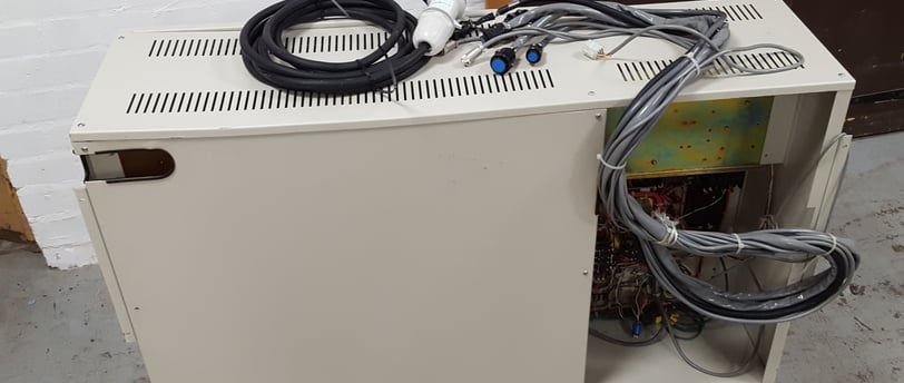
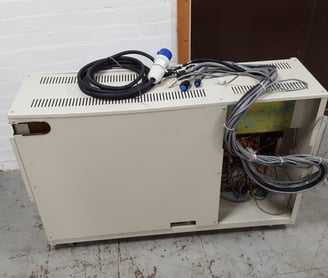
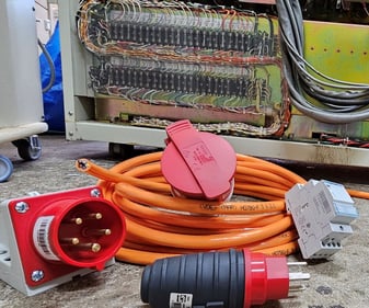
The Sem power supply is a completely ridiculous object. To simplify the diagram as much as possible, it consists of 5 transformers: one produces 100V for the pre-vacuum pump and 220V for the diffusion pumps. Another one provides 5V and two lines at 24V for the vacuum control circuit and the electro-pneumatic valves of the electro-optical column. The remaining two transformers globally produce about forty different voltages used in various subsystems of the instrument. It is a strictly linear system with diode bridges and capacitors as big as a can of your favorite carbonated beverage! The whole thing weighs 140 kg! When connected to your power socket, it consumes a whopping 6 KW, all included...
The problem is that in Switzerland and everywhere in the world, you can't just plug in such a device to your Chinese multi-socket power strip! In Switzerland, electrical installations are specific! Everyone has from 30 to 45 amperes distributed across three phases, with 10-15 amperes each.
In order to power Sem, its power supply needs to be modified to work in three phases... but how?
If Sem were still in service, facing a similar question, Jeol System Expert would probably laugh as never in his life and consider the operation impossible! Since Sem lives in my garage I am the one deciding what can be done and what cannot! Various hypotheses are available:
Increase the installed power to feed Sem on a single 30 Amperes phase. Easy, but in Switzerland, such a maneuver costs a fortune and would be strongly illegal to use the three phases in such an imbalanced way.
Use a phase adder transformer: three-phase primary with 10 amperes each, single-phase secondary with 30 amperes. Nice idea, but such a large transformer, a 6 KW one, would cost 3 or 4 times what I paid for Sem.
Rewind the 4 transformers to work in three phases: the operation would be elegant in itself. But the different primaries are controlled by a series of relays that would need to be modified accordingly. Besides, having four transformers of this size rewound scares me; it would cost a fortune.
Cheat!!!!
And since I'm a bit short on resources, let's go with option 4!!!! After studying the electrical diagram of the power supply, it is clear that the pumps' transformers and the logic circuits of the electro-optical column, namely T1 and T4, are powered first. Through relay RY3, T2 and T3 are then powered to supply all the subsystems of the instrument.
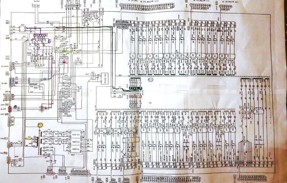
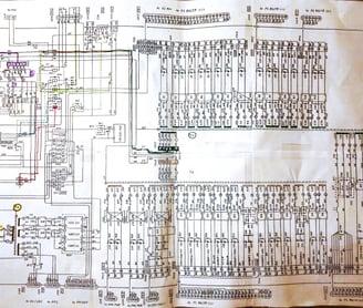
The plan is as follows: leave T1 and T4 connected to L1, the first phase of my electrical system. RY3 will power a 4-pole contactor that switches L2 to T2 and L3 to T3.
The whole setup will be slightly unbalanced, with L1 being a bit more loaded than L2 and L3, but in theory, it should work. The three groups of transformers seem to be completely independent, and each phase of the direct current systems is heavily filtered; therefore, I hope there won't be any problems due to phase shift between the primaries...
What do you think? If you have any suggestions, please write to drgab@semgarage.com.